Were the original Vox AC15's wired correctly?

Anything to do with Fender, Burns and other guitars; also amps, effects units including eTap, plus any other music making accessories

Moderators: David Martin, dave robinson, Iain Purdon, George Geddes

Were the original Vox AC15's wired correctly?

Postby almano » Tue Jun 22, 2010 7:40 pm

Hi, you may have read from my other postings that I’m renovating a lot of guitar gear that’s been in storage for a good number of years.

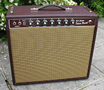
Well, one of the items I’m sorting out at the moment happens to be an original Vox AC15 from either 1959 or 1960. As I’m proceeding with the refurbishment I’m taking photos along the way as a record of the procedure.

Now, a strange thing (a conundrum I suppose really) with this amp is that, although I’ve got copies of the original circuit diagrams (schematics) – when I check out the original wiring I find that it was actually wired incorrectly when it was built fifty years ago! If this wiring error proves to be similar for all the production run in those early days – could it perhaps explain why HBM got the sound he did on all those ‘60’s recordings?

The amp obviously would still have worked reasonably well, but the resulting sound would have been just that little bit different to what its designer originally intended. Could this be the key to that elusive Hank sound we all now search for? I wonder!

Anyway, to illustrate what I mean, I’m including a couple of photos of the circuitry around the two EL84 output stage.

I’m afraid that you’ll now have to excuse me for being a bit technical, but it’s the only way I can describe the wiring error correctly.

What has happened is that a 100 ohm resistor (it’s the brown / black / brown / silver banded resistor) that is supposed to feed buffered HT to the screen grid (G2) of each EL84 (each valve has one of these resistors) has incorrectly been wired in series with the output transformer primary feeds to the EL84 anodes. The screen grids (G2) have then been fed directly with raw HT from the main smoothing block instead of from HT supplied through the 100 ohm resistors. A thought then occurred to me that, although these are output pentodes and have the extra grid to stop this sort of thing, I wonder if the DC conditions could induce a sort of Miller effect that would bounce back a larger percentage of electron flow from G2 to G1 than was originally intended? Alright, I know the Miller effect is more or less a sort of internal capacitance problem between the valves’ electrodes - and pentodes are intended to prevent this problem – but it’s this sort of technical equation that could inadvertently give rise to some interesting sounds in the final mix.

If you look at the photos below and would like to check it out for yourself, the pin numbers of the EL84 output valves counting clockwise are: pin 2 = input grid, pin 3 = common cathode, pins 4 & 5 = heaters, pin 7 = anode, pin 9 = G2 / screen grid. – Pins 1, 5, 8 are not connected.

This now presents me with yet another dilemma – do I change the circuitry to correspond with the original circuit diagrams – or again, do I leave it “as is” and get the “technically incorrect” Hank sound (assuming Hank’s early AC15 was also wired the same) – what the heck do I do?

Once again, any advice and guidance would be very, very gratefully received – I just don’t know what to do for the best!

Cheers,

Alan.

Image

Image
almano
 

Re: Were the original Vox AC15's wired correctly?

Postby Twang46 » Tue Jun 22, 2010 8:21 pm

Hi Alan

I would try & see as many AC15's as possible, either first hand or by asking members etc... to photograph their amps to see if yours is a "one off" or were they all the same until the "fault" was noticed. ?
Depending on the results of your survey you really could be on to something very interesting here!

Cheers

Dick.
Twang46
 
Posts: 446
Joined: Wed Sep 16, 2009 6:21 pm
Location: Co Durham. U.K.
Full Real Name: Dick Cruddas

Re: Were the original Vox AC15's wired correctly?

Postby dave robinson » Wed Jun 23, 2010 12:45 am

I imagine Roger Alcock could answer this question as he has worked on original ones and built these amps in the past . . . . . .
Dave Robinson
User avatar
dave robinson
 
Posts: 5949
Joined: Wed Sep 09, 2009 2:34 pm
Location: Sheffield
Full Real Name: David Robinson

Re: Were the original Vox AC15's wired correctly?

Postby rogera » Wed Jun 23, 2010 8:10 am

Although I have built amps of this type, I've kept to the circuitry shown on the original Vox drawings.

My experience of working on an original AC15 did'nt involve the output section of the circuit which is the part that Alan is talking about, but I would say that if the amp left the works like that then it was most definitely an error.

It certainly would be interesting to hear if there are any other original amps of this type to find out if the 'mistake' was a one-off.

My own thoughts on the change picked up by Alan is that it would not change the character of the sound from the amp other than to reduce the output by a very small amount. However, when I get an opportunity I will try this change on my own AC15 out of interest.
User avatar
rogera
 
Posts: 1087
Joined: Wed Sep 16, 2009 1:06 pm
Location: South West
Full Real Name: Roger Allcock

Re: Were the original Vox AC15's wired correctly?

Postby almano » Wed Jun 23, 2010 10:21 am

Hi Roger, it will be very interesting to have your input to this wiring problem, especially as you have firsthand practical knowledge of Vox amplifier building techniques.

My valve theory is a little (probably a lot these days!) rusty now, but I do seem to remember being taught that output pentodes (EL84’s & EL34’s etc) and tetrodes (KT66 & 6L6GC’s and suchlike) were usually set with the G2 (screen grid) operating at a slightly lower voltage than the anode. The third grid (or plate in the case of beam tetrode power valves) was there to prevent some sort of reaction (reverse I believe) between the anode and the screen grid. Possibly, I’m assuming, the slightly higher voltage seen on the G2 screen grid as opposed to the voltage on the anode could give rise to some form of unforeseen distortion (not significant as such, but there nonetheless) – and also, as you say Roger, most likely a small reduction in the output volume.

If you do mod your amp to test out this anomaly, I’d be most interested to hear what you think – will it produce that elusive sound – or will it most probably just give a reduction in output as you mentioned? I await your feedback with eager anticipation. It will certainly help me to decide whether to leave the amp in its “incorrect” condition – or put it right as per the circuit diagram.

As you can see from the photos, the amp is untouched – it’s “as was supplied” – but it certainly sounded “sweet and clear” when it was last used. It was actually matched with a blue Vox 12” speaker in one of the old Jennings cabinets – that still exists as well! Actually, something else that is a little odd is that, although both amp and speaker cabinets have VOX badges on them; the JMI logo is very visible on the amp’s control panel. Does this help to give an accurate date to the amp? I’ve been assuming the true original date of the amp because of the late fifties date stamp on one of the large capacitors – but of course I could easily be wrong – so any advice there would be very helpful in determining its actual age, but all the clues do point to around ’59 – ’60 with perhaps a year or so either way.

I’ve also got a Marshall JTM45 of a nearly similar vintage I’ll be trying to get going again – but there’s no cabinet work with that one – it’s just the innards that are left. However, they are all there – just one of the KT66’s is missing. I somehow don’t think this one will produce convincing clear Shad’s sounds though, just more raucous noises instead I would imagine!

Thanks to everyone for your advice and help, it’s much appreciated.

Cheers,

Alan.
almano
 

Re: Were the original Vox AC15's wired correctly?

Postby Amanda » Wed Jun 23, 2010 10:52 am

Hi All,
It's not a wiring problem.

The amp is correct, in the circuit diagram OS/005 of 4/12/1959 the resistors are in the anodes.

On Page 360 of Jim Elyea's Vox book there is a photo of the underside of the chassis
of the second circuit TV front chassis, this chassis has the simplified vib / trem using an ECF82 valve
and has a smaller single tagboard on the preamp section.

Also from the book this chassis was used in the first half of 1960, thus dating your amp to early 1960.

Justin Daish's 1960 AC15 has the No. 3 circuit and is from the latter half of 1960.

Amanda
[Check Out My Meazzi Site: http://www.meazzi.org.uk
And Tape Echo Forum: http://ac15.org.uk/meazzibbs/index.php

You're Never Alone With A Mitzi!
User avatar
Amanda
 
Posts: 967
Joined: Sat Sep 12, 2009 11:55 am
Full Real Name: Amanda Hambidge

Re: Were the original Vox AC15's wired correctly?

Postby ernie1958 » Wed Jun 23, 2010 11:44 am

rogera wrote:
It certainly would be interesting to hear if there are any other original amps of this type to find out if the 'mistake' was a one-off.

Ask Justin Daish or Phil Kelly...they seem to have the same kind of AC15... :mrgreen:
Btw Roger...just out of curiosity..is the re-issue AC15 wired the same way as the original and most important..does it SOUND the same?
I still haven't had the opportunity to try one out myself yet,that's why i ask..

Cheers,
Ernie
ernie1958
 

Re: Were the original Vox AC15's wired correctly?

Postby almano » Wed Jun 23, 2010 4:58 pm

Many thanks to everyone for all the info on the old Vox AC15 – especially Amanda for confirming that the wiring is indeed correct. This means that I can leave the wiring as it is without feeling any pangs of guilt that things are not right – what a relief!

I’m still puzzled though as to why Vox would have chosen to use such a strange piece of circuitry around the output valves – they obviously went the conventional route with later revisions – but what was their thinking at the time? Was there a problem of sorts with the output transformers of the period causing some instability and thereby requiring the 100 ohm resistor to be in series with the anode feed from the transformer primary – perhaps in the same manner as a grid stopper resistor is used to prevent parasitic oscillations? I haven’t seen such resistors used in other EL84 output circuits – but I’m happy to be proved wrong – you’re never too old to learn something new!

An interesting aside to this Vox amp story is that, in the late ‘70’s I used to use a Leak TL12+ and a Varislope pre-amp coupled to a 12” Goodmans speaker (of some sort) with a 3” Wharfdale tweeter as my practice rig. Yes, I know it was meant to be hi-fi, but this amp also used a pair of EL84’s – and it used to go louder than you would have expected it too! The Leak Varislope pre-amp had a convenient standard jack socket in its front panel, and the filters and tone controls really gave you lots clean sounds to play with.

The ECC81 has now “gassed” – but the old Leak set up is still intact – so that’s another project to get my teeth into – if I can ever find the time. I have even hung onto an old Vortexion CBL tape recorder – although I imagine that’s probably seized up by now. What a difference though with today’s recordings being carried out at mastering quality on lap tops – no more lugging monstrously heavy recorders around these days! What luxury musicians have now with things like multi track digital recording set ups complete with high quality built in mics, all contained in one compact box small enough to fit in your pocket – we would never have expected that back in the sixties!

Ah, the old times – were things heavier then? – modern guitars seem so much lighter than the old ‘uns – is it conservation, are they saving wood? At least these new ones don’t make your shoulder ache like the old Les Pauls did, jeepers – they were / are heavy!

Cheers,

Alan.
almano
 

Re: Were the original Vox AC15's wired correctly?

Postby Amanda » Wed Jun 23, 2010 5:36 pm

Alan, That leak is worth a small fortune.

I can confirm that Justin's AC15 is a circuit No. 3 amp
having had intimate knowledge of it last November at Reading.

Regarding the Shadows sound, if they used AC30/4's for recordings
then the only difference in sound would have been in theatres when they were
using the TV front amps.

Amanda
[Check Out My Meazzi Site: http://www.meazzi.org.uk
And Tape Echo Forum: http://ac15.org.uk/meazzibbs/index.php

You're Never Alone With A Mitzi!
User avatar
Amanda
 
Posts: 967
Joined: Sat Sep 12, 2009 11:55 am
Full Real Name: Amanda Hambidge

Re: Were the original Vox AC15's wired correctly?

Postby peter roest » Wed Jun 23, 2010 8:50 pm

Hi,

the connection of the screen grid to the output transformer instead of the HT means that the EL84"s are switched as an triode poweramp. That means the power
output is about 50% of the pentode mode. In those years and still now there is (and was) discussion about the quality of triode/pentode amps. For guitaramps the
pentode mode is for years most used. Funny is that the more expensive guitar amps nowadays have the possibility to switch from penthode to triode mode,
also reducing the power to 50% with other harmonic distorsion. In hi-end amps there is a possibility to use the ultra lineair mode in whith an special tap on the
output transformer gives pentode power whith low distorsion.
For me you can connect the 100 ohm resistor to the HT getting more output. By using an switch you can get triode or pentode (more power) mode.

Peter
peter roest
 

Next

Return to Gear

Who is online

Users browsing this forum: No registered users and 86 guests

Ads by Google
These advertisements are selected and placed by Google to assist with the cost of site maintenance.
ShadowMusic is not responsible for the content of external advertisements.